DATA LOG + / DATA LOG 2+
Anuncio
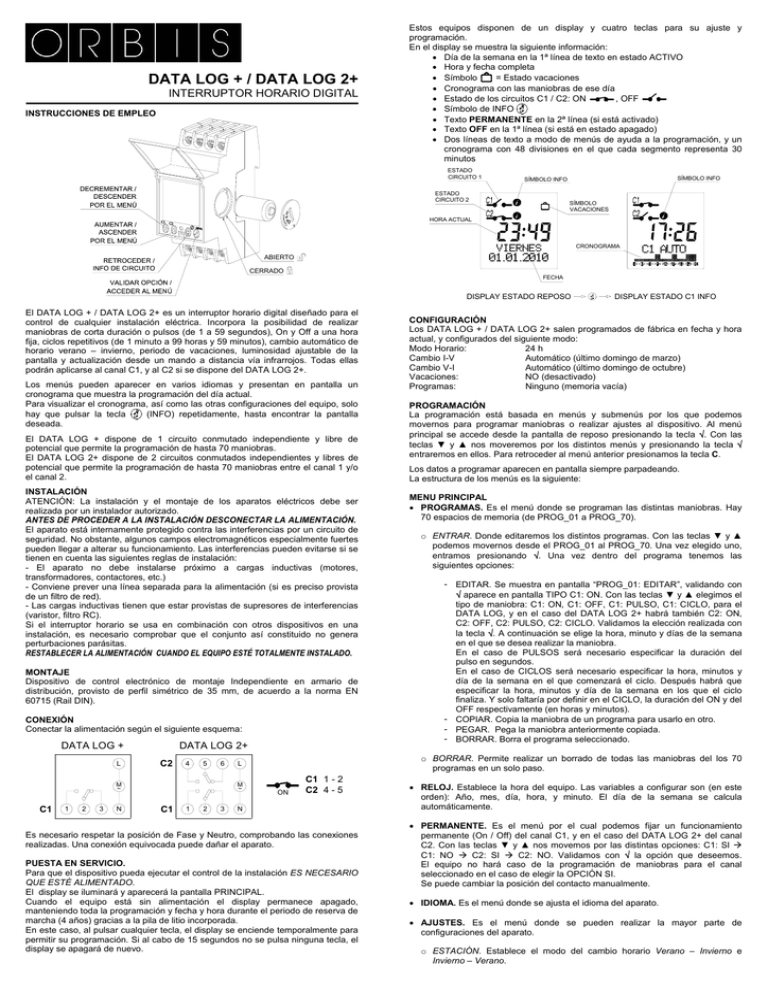
DATA LOG + / DATA LOG 2+ INTERRUPTOR HORARIO DIGITAL INSTRUCCIONES DE EMPLEO Estos equipos disponen de un display y cuatro teclas para su ajuste y programación. En el display se muestra la siguiente información: • Día de la semana en la 1ª línea de texto en estado ACTIVO • Hora y fecha completa = Estado vacaciones • Símbolo • Cronograma con las maniobras de ese día , OFF • Estado de los circuitos C1 / C2: ON • Símbolo de INFO • Texto PERMANENTE en la 2ª línea (si está activado) • Texto OFF en la 1ª línea (si está en estado apagado) • Dos líneas de texto a modo de menús de ayuda a la programación, y un cronograma con 48 divisiones en el que cada segmento representa 30 minutos ESTADO CIRCUITO 1 SÍMBOLO INFO SÍMBOLO INFO ESTADO CIRCUITO 2 SÍMBOLO VACACIONES HORA ACTUAL CRONOGRAMA VIERNES ABIERTO CERRADO FECHA DISPLAY ESTADO REPOSO El DATA LOG + / DATA LOG 2+ es un interruptor horario digital diseñado para el control de cualquier instalación eléctrica. Incorpora la posibilidad de realizar maniobras de corta duración o pulsos (de 1 a 59 segundos), On y Off a una hora fija, ciclos repetitivos (de 1 minuto a 99 horas y 59 minutos), cambio automático de horario verano – invierno, periodo de vacaciones, luminosidad ajustable de la pantalla y actualización desde un mando a distancia vía infrarrojos. Todas ellas podrán aplicarse al canal C1, y al C2 si se dispone del DATA LOG 2+. Los menús pueden aparecer en varios idiomas y presentan en pantalla un cronograma que muestra la programación del día actual. Para visualizar el cronograma, así como las otras configuraciones del equipo, solo hay que pulsar la tecla (INFO) repetidamente, hasta encontrar la pantalla deseada. El DATA LOG + dispone de 1 circuito conmutado independiente y libre de potencial que permite la programación de hasta 70 maniobras. El DATA LOG 2+ dispone de 2 circuitos conmutados independientes y libres de potencial que permite la programación de hasta 70 maniobras entre el canal 1 y/o el canal 2. INSTALACIÓN ATENCIÓN: La instalación y el montaje de los aparatos eléctricos debe ser realizada por un instalador autorizado. ANTES DE PROCEDER A LA INSTALACIÓN DESCONECTAR LA ALIMENTACIÓN. El aparato está internamente protegido contra las interferencias por un circuito de seguridad. No obstante, algunos campos electromagnéticos especialmente fuertes pueden llegar a alterar su funcionamiento. Las interferencias pueden evitarse si se tienen en cuenta las siguientes reglas de instalación: - El aparato no debe instalarse próximo a cargas inductivas (motores, transformadores, contactores, etc.) - Conviene prever una línea separada para la alimentación (si es preciso provista de un filtro de red). - Las cargas inductivas tienen que estar provistas de supresores de interferencias (varistor, filtro RC). Si el interruptor horario se usa en combinación con otros dispositivos en una instalación, es necesario comprobar que el conjunto así constituido no genera perturbaciones parásitas. RESTABLECER LA ALIMENTACIÓN CUANDO EL EQUIPO ESTÉ TOTALMENTE INSTALADO. MONTAJE Dispositivo de control electrónico de montaje Independiente en armario de distribución, provisto de perfil simétrico de 35 mm, de acuerdo a la norma EN 60715 (Rail DIN). CONEXIÓN Conectar la alimentación según el siguiente esquema: DATA LOG + L DATA LOG 2+ C2 4 5 6 M ~ C1 1 2 3 N C1 1 2 3 CONFIGURACIÓN Los DATA LOG + / DATA LOG 2+ salen programados de fábrica en fecha y hora actual, y configurados del siguiente modo: Modo Horario: 24 h Cambio I-V Automático (último domingo de marzo) Cambio V-I Automático (último domingo de octubre) Vacaciones: NO (desactivado) Programas: Ninguno (memoria vacía) PROGRAMACIÓN La programación está basada en menús y submenús por los que podemos movernos para programar maniobras o realizar ajustes al dispositivo. Al menú principal se accede desde la pantalla de reposo presionando la tecla √. Con las teclas ▼ y ▲ nos moveremos por los distintos menús y presionando la tecla √ entraremos en ellos. Para retroceder al menú anterior presionamos la tecla C. Los datos a programar aparecen en pantalla siempre parpadeando. La estructura de los menús es la siguiente: MENU PRINCIPAL • PROGRAMAS. Es el menú donde se programan las distintas maniobras. Hay 70 espacios de memoria (de PROG_01 a PROG_70). o ENTRAR. Donde editaremos los distintos programas. Con las teclas ▼ y ▲ podemos movernos desde el PROG_01 al PROG_70. Una vez elegido uno, entramos presionando √. Una vez dentro del programa tenemos las siguientes opciones: - EDITAR. Se muestra en pantalla “PROG_01: EDITAR”, validando con √ aparece en pantalla TIPO C1: ON. Con las teclas ▼ y ▲ elegimos el tipo de maniobra: C1: ON, C1: OFF, C1: PULSO, C1: CICLO, para el DATA LOG, y en el caso del DATA LOG 2+ habrá también C2: ON, C2: OFF, C2: PULSO, C2: CICLO. Validamos la elección realizada con la tecla √. A continuación se elige la hora, minuto y días de la semana en el que se desea realizar la maniobra. En el caso de PULSOS será necesario especificar la duración del pulso en segundos. En el caso de CICLOS será necesario especificar la hora, minutos y día de la semana en el que comenzará el ciclo. Después habrá que especificar la hora, minutos y día de la semana en los que el ciclo finaliza. Y solo faltaría por definir en el CICLO, la duración del ON y del OFF respectivamente (en horas y minutos). - COPIAR. Copia la maniobra de un programa para usarlo en otro. - PEGAR. Pega la maniobra anteriormente copiada. - BORRAR. Borra el programa seleccionado. o BORRAR. Permite realizar un borrado de todas las maniobras del los 70 programas en un solo paso. L M ~ DISPLAY ESTADO C1 INFO ON C1 1 - 2 C2 4 - 5 N Es necesario respetar la posición de Fase y Neutro, comprobando las conexiones realizadas. Una conexión equivocada puede dañar el aparato. PUESTA EN SERVICIO. Para que el dispositivo pueda ejecutar el control de la instalación ES NECESARIO QUE ESTÉ ALIMENTADO. El display se iluminará y aparecerá la pantalla PRINCIPAL. Cuando el equipo está sin alimentación el display permanece apagado, manteniendo toda la programación y fecha y hora durante el periodo de reserva de marcha (4 años) gracias a la pila de litio incorporada. En este caso, al pulsar cualquier tecla, el display se enciende temporalmente para permitir su programación. Si al cabo de 15 segundos no se pulsa ninguna tecla, el display se apagará de nuevo. • RELOJ. Establece la hora del equipo. Las variables a configurar son (en este orden): Año, mes, día, hora, y minuto. El día de la semana se calcula automáticamente. • PERMANENTE. Es el menú por el cual podemos fijar un funcionamiento permanente (On / Off) del canal C1, y en el caso del DATA LOG 2+ del canal C2. Con las teclas ▼ y ▲ nos movemos por las distintas opciones: C1: SI Æ C1: NO Æ C2: SI Æ C2: NO. Validamos con √ la opción que deseemos. El equipo no hará caso de la programación de maniobras para el canal seleccionado en el caso de elegir la OPCIÓN SI. Se puede cambiar la posición del contacto manualmente. • IDIOMA. Es el menú donde se ajusta el idioma del aparato. • AJUSTES. Es el menú donde se pueden realizar la mayor parte de configuraciones del aparato. o ESTACIÓN. Establece el modo del cambio horario Verano – Invierno e Invierno – Verano. - AUTO. Realiza automáticamente el cambio horario el último domingo de marzo y el último domingo de octubre. - MANUAL. Permite elegir el mes día y hora para realizar el cambio horario. - DESACT. No realiza el cambio horario. o VACACIONES. Es empleado en para escoger un periodo de tiempo (días/meses) en el que el dispositivo permanecerá apagado. El periodo de tiempo empezará a contar a partir de las 00:00:00 horas del día programado de inicio hasta las 23:59:59 del día de finalización. Este periodo se repetirá año tras año. - DESACT. No realiza periodo de vacaciones. - EDITAR. Configura el día de inicio y finalización del periodo de vacaciones. o TECLADO. Menú para la activación o desactivación del bloqueo del teclado para impedir el acceso no deseado a la configuración del aparato. - BLOQ: NO. Bloqueo del teclado desactivado. - BLOQ: SI. Bloqueo del teclado activado. Esta protección se activará 10 segundos después de que salgamos de los ajustes y volvamos al display en estado de reposo. A partir de este momento si se pulsa el teclado aparecerá en pantalla el mensaje “TECLADO BLOQUEADO”. Para desbloquear el teclado tendremos que presionar la siguiente secuencia de teclas: C ▼ ▲ C √ √. Si pulsamos mal la secuencia aparecerá en pantalla el mensaje: “ERROR TECLADO” durante unos pocos segundos. Si por el contrario introducimos bien la secuencia, aparecerá el display del dispositivo en estado de reposo y quedará desprotegido durante 10 segundos. Durante este tiempo podremos acceder al menú de configuración del aparato presionando √. o CONTADOR. Menú en el que se indica el tiempo de encendido de cada circuito (en horas). - BORRAR C1. Pone el contador de horas del canal 1 a cero - BORRAR C2. Pone el contador de horas del canal 2 a cero o INFRARROJO. Para volcado de datos mediante mando a distancia. (Ver apartado VOLCADO DE DATOS MEDIANTE MANDO A DISTANCIA). Esta opción solo funciona cuando el aparato está conectado a la red. o CONTRASTE. Menú en el que podemos seleccionar el contraste del display. - MINIMO, BAJO, MEDIO, ALTO, ó MAXIMO. Al pulsar una tecla, el contraste pasa temporalmente a nivel máximo durante 3 segundos. Si al cabo de ese tiempo no se ha pulsado ninguna tecla, el nivel de contraste se ajustará de nuevo al que estuviera seleccionado. Durante la Programación el display siempre está en nivel máximo. o VERSIÓN. Menú en el que se indica la versión de software del aparato. Si se programan maniobras coincidentes en el tiempo hay que tener en cuenta que unas son prioritarias sobre otras. El orden de prioridad es el siguiente: MODO APAGADO Æ MODO PERMANENTE Æ MANUAL Æ PROG_01 Æ PROG_02 Æ …. Æ PROG_70 ACCIONAMIENTO MANUAL Se pueden activar o desactivar temporalmente el estado de los circuitos desde el modo NORMAL, pulsando la tecla ▼ C1 y ▲ C2. El símbolo aparecerá en pantalla hasta que se realice una maniobra automática programada. Para verificar el estado de un canal, se pulsará la tecla (INFO) hasta que aparezca la información deseada. RESET Pulsar las cuatro teclas simultáneamente hasta que aparezca en el display la versión de software, se borra toda la programación existente y se entra en el modo de funcionamiento normal. Para ejecutar el RESET el equipo debe de estar alimentado. Mediante este mando también es posible volcar toda esta configuración, o únicamente la fecha y hora actual configuradas en el mando. El acceso al control remoto vía infrarrojos puede ser de tres formas diferentes: 1) El DATA LOG + / 2+ en modo normal detecta la comunicación infrarroja de un mando situado enfrente. En ese instante aparecerá el texto “INFRARROJOS PULSE MENU”. Pulsando MENU aparecerá el texto “INFRARROJO ESPERANDO” y en ese momento se podrá empezar la comunicación desde el mando. 2) En modo normal, pulsando más de 3 segundos la tecla MENU, aparecerá el texto “INFRARROJO ESPERANDO” y en ese momento se podrá empezar la comunicación desde el mando. 3) Desde modo normal, pulsando MENU entramos en la selección de menú. Con las teclas ▼ y ▲ seleccionamos el MENU AJUSTES y entramos en él pulsando la tecla MENU. Con las teclas ▼ y ▲ seleccionamos AJUSTES INFRARROJO y entramos pulsando MENU. Dentro de este menú aparecerá el texto “INFRARROJO ESPERANDO” y en ese momento se podrá empezar la comunicación desde el mando. CARACTERÍSTICAS TÉCNICAS Tensión nominal Tolerancia Poder de ruptura: Cargas máximas recomendadas (N.A) Lámparas Incandescentes VOLCADO MEDIANTE MANDO A DISTANCIA Siempre que el DATA LOG + / 2+ esté alimentado podrá ser controlado desde un mando a distancia (vía infrarrojos). Tanto el modelo DATA como GPS SAT del mando a distancia son válidos para el DATA LOG + / 2+. 3000 W Lámparas Fluorescentes 1200 VA Lámparas Halógenas baja tensión 2000 VA Lámparas Halógenas (230 VAC) 3000 W Lámparas de bajo consumo (CFL) 600 VA Lámparas de bajo consumo (Downlights) 400 VA Lámparas LEDs 600 VA Consumo propio Contacto Precisión de marcha Variación de la precisión con la Tª Reserva de marcha Tipo de acción Clase y estructura del software Espacios de memoria Nº de canales Tipos de maniobra Precisión de la maniobra Tª de funcionamiento Tª de transporte y almacenamiento Situación de contaminación Grado de protección Clase de protección Tensión transitoria de impulso Temperatura para el ensayo de la bola Tapa de acceso al teclado Conexión Pila Dimensión de la envolvente Máximo 4,5 VA Inductivos (1,8 W) AgSnO2 conmutado ± 1 s / día a 23 ºC ± 0,15 s / ºC / 24 h 4 años (sin conexión a red) 1S, 1T, 1U Clase A 70 DATA LOG +: 1 ; DATA LOG 2+: 2 HORA FIJA: ON; OFF PULSO: De 1 a 59 segundos CICLO: De 1 minuto a 99 h y 59 min ± 1 segundo -10 ºC a +45 ºC -20 ºC a +60 ºC 2 IP 20 según EN60529 II en montaje correcto 2,5 kV + 83ºC para 21.2.5 Precintable Mediante borne de agujero para conductores de sección máxima 4 mm² ½ AA – 3,6 V – 1000 mAh – Li/SOCi2 2 módulos DIN (35 mm) DIMENSIONES 65 35 60 88 CAMBIO DE PILA El equipo dispone de una reserva de marcha de 4 años, mediante pila de litio sustituible. La sustitución de la pila se realiza extrayendo el botón giratorio situado en el lateral derecho del equipo. Cuando la pila está agotada y el dispositivo no está alimentado aparece en pantalla CAMBIAR BATERIA. NOTA: Al cambiar la pila no se pierde la programación del equipo, pero sí se pierde la hora actual y por tanto, deberemos volver a realizar la PUESTA EN HORA mediante el menú RELOJ. Para abrir la tapa de la pila, girarla mediante una moneda u objeto plano que quepa en su ranura en el sentido contrario a las agujas de un reloj (marcado con una flecha), hasta hacer coincidir el índice de la tapa con el de posición abierto en el aparato. Una vez sustituida la pila, insertar la tapa colocándola de manera que coincida el índice de la tapa con el de posición abierto en el aparato y después girar en el sentido de las agujas de un reloj hasta que el índice de la tapa coincida con el índice de cerrado del aparato (marcado con un candado). PARA LA SUSTITUCIÓN DE LA PILA DESCONECTAR LA ALIMENTACIÓN Según indicación en el aparato ± 10% µ 2x16 (10) A / 250 V~ ATENCIÓN: Este interruptor horario incorpora una pila cuyo contenido puede ser nocivo para el medio ambiente. No se deshaga del producto sin tomar la precaución de desmontar la pila y depositarla en un contenedor adecuado para su reciclaje, o bien remitir el producto al fabricante. Desde el mando es posible leer la configuración del equipo. Esta configuración consta de los siguientes parámetros: - Fecha y hora de los cambios de estación de verano e invierno Intensidad del backlight actualmente seleccionado Idioma Programas Bloqueo de teclado Vacaciones 02/01.2013 A016.17.55502 ORBIS TECNOLOGÍA ELÉCTRICA S.A. Lérida, 61 E-28020 MADRID Tel.: + 34 91 567 22 77 Fax + 34 91 571 40 06 E-mail: info@orbis.es http://www.orbis.es DATA LOG + / DATA LOG 2+ DIGITAL TIME SWITCH INSTRUCTIONS FOR USE These units have an LCD panel and four keys for adjustment and programming. The following information is shown on the LCD: • Day of the week in text line 1 in the ON state • Complete time and date • Symbol = Vacation state • Chronogram with the operations for that day • State of circuits C1 / C2: ON , OFF • INFO symbol • PERMANENT text in line 2 (if activated) • OFF text in line 1 (if in switched-off state) • LOG technology: two text lines for programming help menus • Two lines of text in programming help menu style and a chronogram with 48 divisions in which each segment represents thirty minutes CIRCUIT 1 STATUS INFO SYMBOL INFO SYMBOL CIRCUIT 2 STATUS HOLIDAY SYMBOL DAY OF THE WEEK CURRENT TIME CHRONOGRAM OPEN DATE CLOSE STANDBY STATUS DISPLAY DATA LOG + / DATA LOG 2 + is a digital time switch designed for controlling any electrical installation. It includes the possibility of carrying out short-duration or pulsed operations (from 1 to 59 seconds), On and Off at a set time, repetitive cycles (from 1 minute to 99 hours, 59 minutes), automatic summer/winter time change, holiday (day/month) period, adjustable screen brightness and updating from an infrared remote control. All these features can be applied to channel C1, and to C2 if DATA LOG 2+ is used. Function menus can appear in several languages and they display a chronogram on screen that shows the programming for the current day. To view the chronogram, as well as the other unit configurations, it is only necessary to repeatedly press the key (info) until the desired display is obtained. DATA LOG + has one independent voltage-free switched circuit that allows the programming of up to 70 operations. DATA LOG 2+ has 2 independent voltage-free switched circuits that allow the programming of up to 70 operations between channel 1 and/or channel 2. INSTALLATION WARNING: installation and mounting of electric apparatus shall be carried out by an authorised installer. ALL POWER MUST BE REMOVED BEFORE PROCEEDING WITH THE INSTALLATION,. The unit is internally protected from interference by a safety circuit. However, certain particularly strong fields can alter its operation. Interference can be avoided if the following installation rules are followed: - The unit should not be installed next to inductive loads (motors, transformers and contactors etc.) - It is recommended to provide a separate line for the supply (if necessary, equipped with a mains filter). - Inductive loads must be fitted with interference suppressors (varistor, RC filter). If the time switch is used in combination with other units at an installation, it is necessary to check that the assembly so formed does not generate parasitic interference. THE POWER SHALL ONLY BE RESTORED WHEN THE EQUIPMENT IS COMPLETELY INSTALLED. MOUNTING Electronic control device for independent installation in distribution cabinet fitted with symmetrical 35 mm profile in accordance with the standard EN 60715 (DIN Rail EN 60715 (Rail DIN). CONNECTION Connect the mains supply according to the following schematic: DATA LOG + L DATA LOG 2+ C2 4 5 6 M ~ C1 1 2 3 N C1 1 2 3 CONFIGURATION DATA LOG +/ DATA LOG 2+ units leave the factory configured with the current date and time, and configured as follows: Hour Mode: 24 h W-S Change Automatic (last Sunday of March) S-W Change Automatic (last Sunday of October) Vacations: NO (deactivated) Programs: None (memory empty) PROGRAMMING The programming is based on menus and submenus through which we can move to program operations or make adjustments to the unit. Access to the main menu from the idle screen is by pressing key √. Use the ▼ and ▲ keys to step through the different menus, which can be entered by pressing key √. To go back to the previous menu, press key C. The data to be entered always appear flashing on the screen. The structure of the menus is the following: MAIN MENU • PROGRAMS. This is the menu where the different operations are programmed. There are 70 memory slots (from PROG_01 to PROG_70). o ENTER. Where we will edit the different programs. With the ▼ and ▲ keys, we can step from PROG_01 to PROG_70. After selecting one, it is entered by pressing √. Once inside the program, we have the following options: - EDIT. The message “PROG_01: EDIT” is shown on screen. By validating with √ TYPE C1: ON appears on screen. The type of operation for the DATA LOG is selected with the ▼ and ▲ keys: C1: ON, C1: OFF, C1: PULSE, C1: CYCLE. In the case of DATA LOG 2+, we also have C2: ON, C2: OFF, C2: PULSE, C2: CYCLE. The choice made is validated with key √. Next the hour, minute and combination of days of the week are chosen for the operation. In the case of PULSES, it will be necessary to specify the pulse duration in seconds. In the case of CYCLES, it is necessary to specify when the cycle will begin (hour, minute and day of the week); and then, when the cycle finishes (hour, minute and day of the week). To end the CYCLE definition, it would only remain to indicate the ON period and the OFF period respectively (in hours and minutes). - COPY. It copies the operation of a program for use in another. - PASTE. It pastes the previously copied operation. - ERASE. It deletes the selected program. o ERASE. It allows a deletion to be carried out of all the operations in the programs in one step. • CLOCK. This will set the equipment time. The variables to be configured are (in this order): year, month, day, hour and minute. The day of the week is automatically calculated. L M ~ C1 (INFO) STATUS DISPLAY ON C1 1 - 2 C2 4 - 5 N The Line and Neutral position must be respected, checking the connections made. A wrong connection can destroy the unit. PUTTING IN SERVICE For the device to be able to execute control over the installation, IT MUST BE POWERED UP. The display will light up and the MAIN screen will appear. When the equipment is switched off, the screen will also be off, but the date, time and all programming will be maintained during the four-year lifetime of the incorporated lithium battery. In this case, if any key is pressed, the display will temporarily switch on to allow programming. If no keys are pressed during fifteen seconds, the display will be switched off again. • PERMANENT. This is the menu in which we can fix a permanent operation (On / Off) of channel C1, and of channel C2 in the case of DATA LOG 2+. With the ▼ and ▲ keys we step through the different options: C1: YES Æ C1: NO Æ C2: YES Æ C2: NO. We validate the case we want with √. The equipment will not follow the operations programming for the selected channel if OPTION YES is selected. The contact position can be changed manually. • LANGUAGE. This is the menu where the unit language is set. • SETTINGS. This is the menu in which most of the unit configurations can be carried out. o SEASON. It establishes the time change mode Summer - Winter and Winter - Summer. - AUTO. It automatically carries out the time change on the last Sunday of March and on the last Sunday of October. - MANUAL. It allows the day and time to be chosen for carrying out the time change. - DESACT. The time change is not carried out. o HOLIDAYS. This is employed to choose a date period (day/month) on which the unit will be deactivated (switched off). This period will repeated year by year and begin to count from the 00:00:00 hours of the start day until the 23:59:59 hours of the end day. - DEACT. No holiday adjustment. - EDIT. Configure the start day and the end day of the holiday lapse. o KEYBOARD. Menu to activate or deactivate the keyboard blocking protection to prevent unwanted access. - BLOCK: NO. Protection is disabled. - BLOCK: YES. Protection is enabled. This protection is automatically activated 10 seconds after entering into MAIN screen mode. If keyboard is pressed, message KEYBOARD BLOCKED is displayed. At this point, in order to grant access and clears the protection, next keyboard sequence must be pressed: C ▼ ▲ C √ √. If a wrong sequence is pressed, message KEYBOARD ERROR will be displayed during several seconds. If correct sequence is pressed, NORMAL mode will be displayed and the device will be unprotected for 10 seconds. During this lapse, access to MENU functions is granted by pressing √. o COUNTER. Menu in which we will be able to know the ON-time (in hours) of each channel. - ERASE C1. It puts the hour counter of channel 1 to zero - ERASE C2. It puts the hour counter of channel 2 to zero o INFRARED. For data downloading using the remote control, see the section DATA DOWNLOADING WITH THE REMOTE CONTROL). This option only works when the appliance is connected to the power mains. o CONTRAST. Menu in which we can increase or reduce the display contrast. - MINIMUM, LOW, MEDIUM, HIGH, MAXIMUM When a key is pressed, the contrast will rise to the maximum level for three seconds. If no key has been pressed at the end of this time, the contrast will return to the previously selected value. The display is always at maximum contrast during programming. o VERSION. This indicates the installed software version. If operations are programmed that coincide in time, it must be taken into account that some take priority over others. The priority order is as follows: OFF MODE Æ PERMANENT MODE Æ MANUAL ÆPROG_01 Æ PROG_02 Æ …. Æ PROG_70 The data to be programmed always appear on screen in flashing mode. MANUAL OPERATION The status of the circuits may be temporarily activated or deactivated when in NORMAL mode by pressing the▼ C1 and ▲ C2 keys. The symbol will appear on the screen until a programmed automatic operation takes place. Once changed, it is possible to return to NORMAL mode by repeatedly pressing C. key (INFO) should be pressed until the desired To verify channel status, the information appears. RESET Pressing the four keys at the same time until START AT appears on the display will delete all existing programming and the LANGUAGE MENU operating mode will be entered. The unit must be switched on in order to execute RESET. PRESS MENU” to appear on the screen. Communications with the remote control can now take place. 2) In normal mode, pressing the MENU key for more than three seconds will display the text “INFRARED WAITING”. Pressing MENU will provide access to this function. 3) Pressing MENU in normal mode will enter menu selection. The ▼ and ▲ keys are used to select MENU ADJUSTMENTS and MENU is pressed again to enter this option. The ▼ and ▲ keys are used to select INFRARED ADJUSTMENTS and this option is entered by pressing MENU. Entering this menu will display “INFRARED WAITING” and communications are now available with the remote control. TECHNICAL SPECIFICATIONS: Voltage rating Tolerance Breaking power Maximum recommended loads (N.O): As indicated on the unit ± 10% µ 2x16 (10) A / 250 V~ Incandescent lamps 3000 W Fluorescent lamps 1200 VA Low-voltage halogen lamps 2000 VA Halogen lamps (230 Vac) 3000 W Low-consumption lamps (CFL) 600 VA Low-consumption lamps (Downlights) 400 VA LED lamps 600 VA Self-consumption Contact Operational accuracy Variation of accuracy with temp. Running reserve Type of action Software class and structure Memory slots Nº of channels Types of operation Operating precision Operating temperature Transport and storage Temp Contamination situation Protection degree Protection class Transient pulse voltage Ball test temperature Keypad accesses cover Connection Battery Casing dimensions Maximum 4.5 VA Inductiv (1.8 W) AgSnO2 switched ± 1 s/day at 23 ºC ± 0.15 s / ºC / 24 h 4 years (without mains supply connection) 1S, 1T, 1U Class A 70 DATA LOG+: 1; DATA LOG 2+: 2 FIXED TIME: ON; OFF Pulse: from 1 to 59 seconds Cycle: from 1 minute to 99 hours, 59 minutes ± 1 second -10 ºC to +45 ºC -20 ºC to +60 ºC 2 IP 20 as per EN60529 Class II in proper assembly 2.5 kV + 83 ºC for 21.2.5 Lockable By means of needle post for maximum cable section of 4 mm² ½ AA – 3.6 V – 1000 mAh – Li/SOCi2 2 DIN modules (35 mm) DIMENSIONS 65 35 60 88 BATTERY CHANGE The unit has an operational 4-year backup using a replaceable lithium battery. Replacement of the battery is carried out by withdrawing the rotating button located on the right side of the unit. When the battery is exhausted and the device is not powered up “REPLACE BATTERY” is shown on the screen. NOTE: When changing the battery the unit programming is not lost, however the current time is lost. So we have to carry out the TIME SETTING again by means of the CLOCK menu. The battery cover is opened by rotating it counter-clockwise (marked by an arrow) with a coin or other flat object inserted into its slot, until the cover index coincides with the open position on the unit. After replacing the battery, the cover is inserted by placing it in the same position with the cover index coinciding with the open position on the unit and then turning it clockwise until the cover index coincides with the closed position on the unit. SWITCH THE UNIT OFF WHEN REPLACING THE BATTERY DATA-DOWNLOADING WITH THE REMOTE CONTROL Provided the DATA LOG + / 2+ is powered up, it can be controlled using an infrared remote control. Both the DATA and GPS SAT remote control models can be used with the DATA LOG + / 2+. This control can be used to read the equipment configuration, which will consist of the following parameters: - WARNING: This time switch incorporates a battery, the contents of which may be hazardous to the environment. The unit must not be discarded without taking the precaution to remove the battery and deposit it in a suitable container for recycling or returning it to the manufacturer. Dates and times for summer and winter times changes Currently selected backlight intensity Language Programs Keyboard blocking selection Holidays (start and end dates) This control can also be used to download all this configuration or just the current date and time. Infrared remote control access can be achieved in three different ways: 1) In normal mode, the DATA LOG + / 2+ detects infrared communication from a control positioned in front and pressing MENU will cause the text “INFRARED 02/01.2013 A016.17.56476 ORBIS TECNOLOGÍA ELÉCTRICA S.A. Lérida, 61 E-28020 MADRID Tel.: + 34 91 567 22 77 Fax + 34 91 571 40 06 E-mail: info@orbis.es http://www.orbis.es DIGITALE ZEITSCHALTUHR DATA LOG + / DATA LOG 2+ BEDIENUNGSANLEITUNG Auf dem Display wird folgende Information angezeigt: • Wochentag, Datum in der ersten Textzeile im Normalbetrieb. • Uhrzeit und vollständiges Datum • Symbol = Abwesenheitsmodus • Chronogramm mit den für diesen Tag programmierten Schaltvorgängen , OFF • Schaltkreiszustand C1 / C2 : ON • INFO-Symbol • Text für Dauerfunktionen (PERMANENT) in der zweiten Zeile (wenn aktiviert) • Text OFF in der ersten Zeile (im ausgeschalteten Zustand) • Zwei als Programmierungshilfe dienende Textlinien und ein in 48 jeweils 30-minütige Abschnitte geteiltes Chronogramm. ZUSTAND KANAL 1 INFO SYMBOL INFO SYMBOL ZUSTAND KANAL 2 ABWESENHEITS SYMBOL AKTUELLE UHRZEIT CHRONOGRAMM DATUM OFFEN GESCHLOSSEN Die DATA LOG / DATA LOG+ 2 ist eine digitale für die Kontrolle jeglicher Art elektrischer Schaltungen geeignete Zeitschaltuhr mit folgenden Eigenschaften: kurzzeitige oder impulsförmige Schaltvorgänge (zwischen 1 und 59 Sekunden), On und Off zu einer bestimmten Uhrzeit, Wiederholungsschleifen (von 1 Minute bis 99 Stunden und 59 Minuten), automatischer Wechsel von Sommer- auf Winterzeit, Abwesenheitsmodus von 1 bis 99 Tagen, Display-Helligkeitsregulierung und Aktualisierung mittels Infrararot-Fernbedienung. Sämtliche Einstellungen können am Kanal C1 und beim DATA LOG 2 + auch am Kanal C2 vorgenommen werden. Die Menüführung ist mehrsprachig und zeigt im Display ein Chronogramm mit der aktuellen Tagesprogrammierung an. Um das Chronogramm sowie die anderen Einstellungen anzuzeigen muss man nur die Taste (Info) mehrmals drücken bis die gewünschte Anzeige erscheint. Die DATA LOG + verfügt über einen unabhängigen und potentialfreien Schaltkreis, der die Programmierung von bis zu 70 Schaltvorgängen erlaubt. Die DATA LOG 2 + verfügt über 2 unabhängige und potentialfreie Schaltkreise, die die Programmierung von bis zu 70 Schaltvorgängen an den beiden Kanälen 1 und/oder 2 erlauben. INSTALLATION ACHTUNG: Die Installation und die Montage elektrischer Geräte muss grundsätzlich von einem zugelassenen Elektroinstallateur durchgeführt werden. VOR DEM EINBAU BITTE DIE SPANNUNGSZUFUHR ABSCHALTEN! Das Gerät ist durch einen internen Schutzstromkreis gegen Störsignale geschützt. Dennoch gibt es elektrisch starke Felder, die die Funktion beeinträchtigen können. Diese Interferenzen können jedoch unter Beachtung der nachfolgend aufgeführten Einbauhinweise vermieden werden: - Das Gerät nicht in der Nähe induktiver Lasten montieren (wie z. B. Motoren, Trafos, Schaltschützen, usw.). - Für die Versorgung ist es ratsam ein separates Kabel zu verwenden (ggf. mit einem Netzfilter). - Die induktiven Lasten müssen mit Störschutzeinrichtungen (Varistoren, RCFiltern, usw.) ausgestattet sein. Sollte die Zeitschaltuhr zusammen mit anderen Geräten in einer Anlage betrieben werden, so ist zu prüfen, dass die gesamte gebildete Einheit keine Störsignale erzeugt. DIE SPANNUNGSZUFUHR ERST WIEDER HERSTELLEN, WENN DAS GERÄT VOLLSTÄNDIG EINGEBAUT IST! MONTAGE Elektronisches Kontrollgerät für den unabhängigen Einbau im Schaltschrank mittels symmetrischem 35mm-Profil gemäß der Norm EN 60715 (Hutschiene). ANSCHLUSS Versorgungsanschluss gemäß dem folgenden Anschlussschema: DATA LOG + L DATA LOG 2+ C2 4 5 6 M ~ C1 1 2 3 N L M ~ C1 1 2 3 ON C1 1 - 2 C2 4 - 5 N Auf einen korrekten Anschluss von Phase und Nullleiter ist genau zu achten, da bei falschem Anschluss das Gerät beschädigt werden kann! INBETRIEBNAHME Damit das Gerät alle durchgeführten Anschlüsse überprüfen kann, MUSS ES AN DER STROMVERSORGUNG ANGESCHLOSSEN SEIN. Das Display geht an und das HAUPTMENÜ wird angezeigt. Sollte das Gerät nicht angeschlossen sein, bleibt das Display aus; die gesamte Programmierung sowie Datum und Uhrzeit bleiben jedoch durch die integrierte Lithiumbatterie über den Zeitraum der Gangreserve (4 Jahre) erhalten. In diesem Fall geht das Display nach Betätigen einer beliebigen Taste vorübergehend an und ermöglicht so die Programmierung. Wenn innerhalb von 15 Sekunden keine Taste gedrückt wird, geht das Display wieder aus. Dieses Gerät verfügt über vier Tasten zur Einstellung und Programmierung. ANZEIGE RUHEZUSTAND ANZEIGE ZUSTAND C1 INFO EINSTELLUNG Die Geräte DATA LOG +/ DATA LOG 2 + sind werkseitig auf das aktuelle Datum und die Uhrzeit sowie die folgenden Konfigurationen eingestellt: Zeitanzeige: 24 h Umstellung Winter-Sommer: Automatisch (am letzten Sonntag im März) Umstellung Sommer-Winter: Automatisch (am letzten Sonntag im Oktober) Abwesenheit: NEIN (deaktiviert) Programme: Keines (Speicher leer) PROGRAMMIERUNG Die Programmierung des Gerätes erfolgt menügeführt (Menüs und Untermenüs), in denen man Schaltvorgänge programmieren oder diverse Einstellungen durchführen kann. In das Hauptmenü gelangt man ausgehend von der Anzeige im Ruhezustand durch Betätigen der Taste √. Mit den Tasten ▼ und ▲ wählt man zwischen den verschiedenen Menüs und durch Betätigen der Taste √ gelangt man in das jeweilige Menü. Um in das vorherige Menü zurückzukehren, die Taste C drücken. Die zu programmierenden Daten werden auf dem Display immer blinkend angezeigt. Die Menüstruktur ist folgendermaßen aufgebaut: HAUPTMENÜ • PROGRAMME: In diesem Menü werden die verschiedenen Schaltvorgänge programmiert. Es stehen dafür bis zu 70 Speicherplätze zur Verfügung (von PROG_01 bis PROG_70). o EINGABE: Hier werden die verschiedenen Programme bearbeitet. Mit den Tasten ▼ und ▲ kann man zwischen PROG_01 und PROG_70 wechseln. Nach Auswahl des gewünschten Programms die Taste 3 drücken, worauf man in das jeweilige Programm gelangt und folgenden Optionen zur Verfügung stehen: - ÄNDERN: Im Display erscheint “PROG_01: EDITAR”; nach Bestätigung mit der Taste 3 wird TYP C1: ON angezeigt. Beim DATA LOG + mit den Tasten ▼ und ▲ die gewünschte Schaltart auswählen: C1: ON, C1: OFF, C1: PULS, C1: ZYKLUS. Für die DATA LOG 2+ stehen noch zur Auswahl C2: ON, C2: OFF, C2: PULS, C2: ZYKLUS. Die Auswahl mit der Taste 3 bestätigen. Anschließend die Uhrzeit (Stunden, Minuten) sowie die gewünschten Wochentage für diese Schaltart auswählen. Bei Auswahl der Schaltart PULS muss zusätzlich noch die Impulsdauer in Sekunden eingegeben werden. Bei Auswahl der Schaltart ZYKLUS müssen zusätzlich noch die Uhrzeit (Stunden, Minuten) und der Wochentag eingegeben werden, an dem der Zyklus beginnen und enden soll. Danach fehlt dann nur noch die Eingabe der entsprechenden Zyklusdauer in ON und OFF (ebenso in Stunden und Minuten). - KOPIE: Kopiert den Steuervorgang eines Programms, damit er in einem anderen Programm genutzt werden kann. - EINFÜGEN: Fügt den vorher genannten Steuervorgang ein. - LÖSCHEN: Löscht das ausgewählte Programm. o LÖSCHEN: Ermöglicht das Löschen sämtlicher Schaltvorgänge in allen Programmen mit nur einem Befehl. • ZEIT: Hier wird die Uhrzeit des Gerätes eingestellt, wobei folgende Parameter (in dieser Reihenfolge) konfiguriert werden können: Jahr, Monat, Tag, Stunde und Minute. Der Wochentag wird automatisch berechnet. • PERMANENT: In diesem Menü kann eine Dauerfunktion (On / Off) für den Kanal C1 und im Falle der DATA LOG 2 + auch für den Kanal C2 festgelegt werden. Die Programmierung der Schaltvorgänge wird dabei nicht berücksichtigt. Mit den Tasten ▼ und ▲ können die verschiedenen Optionen ausgewählt werden: C1: JA Æ C1: NEIN Æ C2: JA Æ C2: NEIN. Durch Drücken der Taste √ wird die Einstellung bestätigt. Bei Auswahl der Option JA werden die programmierten Steuervorgänge für den gewählten Kanal vom Gerät ignoriert. Die Kontaktposition kann manuell geändert werden. • SPRACHE: In diesem Menü wird die Sprache ausgewählt. • EINSTELLEN: In diesem Menü kann die Mehrzahl der Gerätekonfigurationen eingestellt werden. o JAHRESZEIT: Legt den Umstellmodus für Sommer- auf Winterzeit und Winter- auf Sommerzeit fest. - AUTO: Die Zeit wird automatisch jeweils am letzten Sonntag im März und Oktober umgestellt. - MANUELL: Damit kann man manuell den für die Umstellung gewünschten Monat, Tag und die Uhrzeit einstellen. - STOP: Bei dieser Einstellung erfolgt keine Zeitumstellung. o FERIENPROGRAMM. Mit diesem Programm kann für einen zu wählenden Zeitraum (Tag/Monat) das Gerät deaktiviert werden (OFF geschaltet). Dieser Zeitraum wird jedes Jahr wiederholt und beginnt bei 00:00:00 Uhr des Starttages bis 23:59:59 Uhr des Endtages. - DEACT. Kein Ferienprogramm. - EDIT. Geben Sie den Starttag und den Endtag der Ferienperiode ein. o TASTATUR. Menü zum Aktivieren oder Deaktivieren der Tastatur, Blockierschutz um unerlaubten Zugriff zu vermeiden. - BLOCK: NO. Schutz ist nicht aktiviert. - BLOCK: YES. Schutz ist aktiviert. Dieser Schutz wird automatisch beim Start des Hauptbildschirms 10 Sekunden lang aktiviert. Wenn eine Taste gedrückt wird, erscheint auf dem Display die Anzeige KEYBOARD BLOCKED. Um den Schutz auszuschalten muss folgende Tastenfolge gedrückt werden: C ▼ ▲ C √ √. Wenn eine falsche Tastenfolge eingegeben wird, erscheint die Anzeige KEYBOARD ERROR für einige Sekunden angezeigt. Wenn eine korrekte Tastenfolge eingegeben wird, wird NORMALER Modus angezeigt und das Gerät ist für 10 Sekunden ungeschützt. Während dieser Zeit hat man Zugang zu den MENÜ Funktionen durch Drücken der Taste √ . o ZÄHLER: In diesem Menü kann man die Betriebszeit (in Stunden) jedes Kanals ablesen. - C1 LÖSCHEN: Setzt den Stundenzähler von Kanal 1 auf 0 - C2 LÖSCHEN: Setzt den Stundenzähler von Kanal 2 auf 0 o INFRAROT: Für die Übertragung der Daten mit einer Fernbedienung. (Siehe hierzu den Abschnitt DATENÜBERTRAGUNG MITTELS FERNBEDIENUNG). Diese Option funktioniert nur wenn der Apparat mit dem Stromnetz verbunden ist. o KONTRAST: Hier kann man den Kontrast der Anzeige folgendermaßen einstellen: - MIN, TIEF, MITTEL, HOCH, MAX. Durch Drücken einer Taste geht der Kontrast zunächst für 3 Sekunden auf den Maximalwert. Sollte in dieser Zeit keine Taste gedrückt werden, stellt sich der Kontrast wieder auf den vorher ausgewählten Wert ein. Während der Programmierung ist grundsätzlich der Maximalwert eingestellt. Auswahl der Tastaturblockierung Ferienprogramm (Start- und Enddatum) Mit dieser Fernbedienung können sämtliche Einstellungsparameter oder aber nur das aktuelle Datum und die Uhrzeit übertragen werden. Der Zugang mittels Infrarot-Fernbedienung kann auf drei unterschiedliche Arten erfolgen: 1) Das Gerät erkennt im Normalbetrieb die Infrarotverbindung der davor gehaltenen Fernbedienung. In diesem Moment erscheint auf dem Display die Meldung (INFRAROT, PRESS MENÜ). Nach Drücken auf MENÜ erscheint (INFRAROT, WARTEN) und ab diesem Zeitpunkt kann man von der Fernbedienung aus mit der Kommunikation beginnen. 2) Wenn man im Normalbetrieb mehr als 3 Sekunden die Taste MENÜ drückt erscheint die Meldung (INFRAROT, WARTEN) und ab diesem Zeitpunkt kann man von der Fernbedienung aus mit der Kommunikation beginnen. 3) Im Normalbetrieb die Taste MENÜ drücken. Mit den Tasten ▼ und ▲ das Menü EINSTELLEN auswählen und wieder die Taste MENÜ drücken. Mit ▼ und ▲ (INFRAROT-EINSTELLEN) auswählen und die Taste MENÜ drücken. Innerhalb dieses Menüs erscheint die Anzeige (INFRAROT, WARTEN) und ab diesem Zeitpunkt kann man von der Fernbedienung aus mit der Kommunikation beginnen. TECHNISCHE DATEN Nennspannung Toleranz Schaltleistung Empfohlene Höchstlasten (N.O): Glühlampen 3000 W Leuchtstofflampen 1200 VA NV-Halogenlampen 2000 VA Halogenlampen (230 VAC) 3000 W Stromsparlampen (CFL) 600 VA Stromsparlampen (Downlights) 400 VA LED-Lampen 600 VA Eigenverbrauch Kontakt Ganggenauigkeit Temperaturabhängige Anz.abweichung Gangreserve Schaltart: Softwareklasse und -struktur Speicherplätze Anzahl Kanäle Steuerungsarten o VERSION: Hier wird die aktuell geladene Software-Version angezeigt. MANUELLE BETRIEBSART Im NORMALBETRIEB kann man vorübergehend den Zustand der Schaltkreise durch Betätigen der Tasten ▼ C1 und ▲ C2 aktivieren oder deaktivieren, worauf im Display das Symbol angezeigt wird. Dieser Zustand wird bis zum nächsten programmierten Schaltvorgang aufrecht erhalten. Um den jeweiligen Schaltzustand eines Kanals anzuzeigen, die Taste (INFO) drücken bis die gewünschte Information erscheint. RESET Durch gleichzeitiges Drücken der vier Tasten bis im Display BEGINNEN angezeigt wird löscht man die gesamte Programmierung und das Menü SPRACHE wird angezeigt. Für diese Funktion muss das Gerät an der Stromversorgung angeschlossen sein. BATTERIEWECHSEL Das Gerät ist mit einer austauschbaren Lithium-Batterie ausgestattet, die eine Gangreserve von 4 Jahren garantiert. Der Austausch der Batterie erfolgt durch Herausziehen des auf der rechten Seite befindlichen Drehknopfes. Wenn die Batterie nahezu leer und das Gerät nicht an der Stromversorgung angeschlossen ist, erscheint die Anzeige (BATTERIE WECHSELN). HINWEIS: Ein Austausch der Batterie hat nicht den Verlust der programmierten Einstellungen, jedoch der Uhrzeit zur Folge, weshalb diese im Menü ZEIT wieder neu eingestellt werden muss. Um den Batteriedeckel zu öffnen, diesen mithilfe einer Münze oder eines passenden flachen Gegenstandes entgegen dem Uhrzeigersinn (in Pfeilrichtung) drehen, bis die Markierung auf dem Deckel mit dem Auf-Symbol übereinstimmt. Nach dem Batteriewechsel den Deckel wieder so einsetzen, dass die Markierung auf dem Auf-Symbol steht und im Uhrzeigersinn drehen, bis die Markierung mit dem Zu-Symbol übereinstimmt (Symbol Vorhängeschloss). BEIM BATTERIEWECHSEL DAS GERÄT VON DER STROMVERSORGUNG TRENNEN! DATENÜBERTRAGUNG MITTELS FERNBEDIENUNG Sofern das DATA LOG + / 2+ an der Stromversorgung angeschlossen ist, kann es mit einer (Infrarot) Fernbedienung programmiert werden. Sowohl das Modell DATA als auch GPS SAT sind für ein Fernbedienung des DATA LOG + / 2+ geeignet. An der Fernbedienung kann man die Einstellparameter des Gerätes ablesen, welche sind: Datum und Uhrzeit der Sommer- / Winterzeitumstellung Aktuell ausgewählte Hintergrundbeleuchtung Sprache Programme Schaltgenauigkeit Betriebstemperatur Transport- und Lagertemperatur Verschmutzungsgrad Schutzart Schutzklasse Stoßspannung Temperatur für Kugeldruckprüfung Schutzklappe für Tastenfeld Anschluss Batterie Gehäuse Max. 4,5 VA induktiv (1,8 W) AgSnO2 Umschaltkontakt ± 1 s/Tag bei 23 ºC ±0,15 s / ºC / 24 h 4 Jahre mittels (austauschbarer) Typ 1S, 1T, 1U Klasse A 70 DATA LOG + 1; DATA LOG 2 + 2 FESTZEIT: ON/OFF IMPULSE: Von 1 bis 59 Sekunden ZYKLEN: Von 1 Minute bis 99 Stunden und 59 Minuten ± 1 Sekunden -10 ºC bis +45 ºC -20 ºC bis +60 ºC 2 IP 20 nach EN 60529 II bei ordnungsgemäßem Einbau 2,5 kV + 83º für 21.2.5 Plombierbar Mittels Buchsenklemme für Kabel mit einem max. Querschnitt von 4 mm² ½ AA – 3,6 V – 1000 mAh – Li/SOCi2 2 Teilungseinheiten (35 mm) BEZUGSRICHTLINIEN UND -NORMEN Richtlinie 2004/108/CE (EMV) (Elektromagnetische Verträglichkeit) Richtlinie 2006/95/CE (LVD) (Niederspannung) UNE-EN 60730-2-7 Automatische elektrische Regel- und Steuergeräte für den Hausgebrauch und ähnliche Anwendungen. Teil 27: Besondere Anforderungen an Zeitsteuergeräte und Schaltuhren. ABMESSUNGEN 65 60 35 88 Sollten sich bei der Programmierung Schaltvorgänge zeitlich überschneiden, so ist zu berücksichtigen, dass in diesem Fall automatisch Prioritäten nach der folgenden Rangfolge gesetzt werden: MODUS INAKTIV Æ MODUS PERMANENT Æ MANUELL ÆPROG_01 Æ PROG_02 Æ …. Æ PROG_70 Gemäß Geräteangabe ± 10% μ 2x16 (10) A / 250 V~ ACHTUNG: Diese Zeitschaltuhr ist in den Modellen mit Gangreserve mit einer Batterie ausgestattet, die umweltschädlich sein kann. Entsorgen Sie nicht das Produkt ohne vorher die Batterie zu entnehmen und in einem entsprechenden Sammelbehälter zu geben oder schicken Sie uns das komplette Produkt zurück. 02/01.2013 A016.17.56475 ORBIS TECNOLOGÍA ELÉCTRICA S.A. Lérida, 61 E-28020 MADRID Tel.: + 34 91 567 22 77 Fax: + 34 91 571 40 06 E-Mail: info@orbis.es http://www.orbis.es
